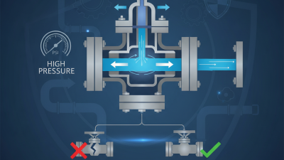
Why Choose a Pneumatic Valve?
Why choose a pneumatic valve? A practical answer begins with the application, not the sales brochure. In factories, compressed air can move a valve actuator quickly, even where electric power needs careful protection. A well-selected pneumatic valve may deliver repeatable movement for process lines, packaging equipment, and fluid control systems. It also offers a simple visual check: the actuator moves, or it does not. That clarity helps technicians during routine inspections.
In my experience, reliable valve selection depends on more than pressure and pipe size. Engineers should examine air quality, operating temperature, cycle frequency, media compatibility, and available maintenance skills. A dusty workshop may need better filtration. A fast production line may require a stronger actuator and suitable response control. Stainless steel bodies can support demanding environments, but material choice still depends on the fluid. Small details matter. Incorrect sizing can cause leakage, slow movement, or unnecessary air consumption. Those problems rarely appear in a product photograph.
Pneumatic systems also have limits. They need a dependable compressor, clean air, and regular inspection. Air leaks may remain unnoticed while energy costs increase. Noise can become another concern without proper exhaust silencers. No valve is perfect. The right choice balances speed, safety, durability, control accuracy, and total operating cost. Specifications should be checked against manufacturer data and recognized engineering practices. When uncertain, consult a qualified professional and test the valve under realistic conditions. A careful decision may take longer, but it usually prevents expensive interruptions later.
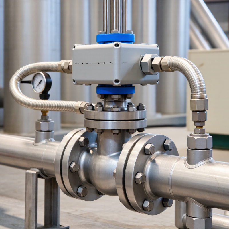
Pneumatic Valve Fundamentals: Compressed-Air Operation at 4–10 bar
Why Choose a Pneumatic Valve?
Pneumatic valves use compressed air to control fluid or gas movement. In many industrial systems, operating pressure falls between 4 and 10 bar. This range supports quick actuation, clean operation, and dependable cycling. A typical setup includes an air compressor, filter, regulator, tubing, actuator, and control valve. Each part affects the final result.
At 4 bar, an actuator may produce less force than expected. At 10 bar, seals and components face greater stress. The working pressure must match the valve design and actuator requirements. A pressure regulator helps maintain stability when the supply fluctuates. A gauge makes hidden problems visible. Air quality matters too. Moisture can damage internal parts, while oil may affect sensitive seals.
In field installations, incorrect sizing remains a common issue. Engineers should check flow rate, pressure drop, temperature, media compatibility, and switching frequency. The actuator also needs enough torque at the lowest available pressure. Faster is not always better. Excessive speed can cause water hammer, vibration, or premature wear. I have seen pressure settings copied from older equipment without checking current conditions. That shortcut can work, but it is not reliable engineering. Regular leak testing, filter draining, and seal inspection help preserve performance. Small leaks become expensive.
Response Speed and Flow: Typical Actuation Times of 10–50 ms
Why choose a pneumatic valve? Response speed is often the practical answer. Typical actuation times range from 10 to 50 milliseconds in compact pneumatic systems. That equals 20 to 100 switching cycles per second, under suitable conditions. ISO 12238 defines methods for measuring directional valve transition time. ISO 6358-1 also evaluates airflow through sonic conductance and critical pressure ratios. These standards show why timing cannot be judged from the valve alone.
In real installations, a short air tube can noticeably improve response. A 100-millimeter connection behaves differently from a one-meter connection. Pressure, exhaust resistance, seal friction, and cylinder load also change the result. A 10-millisecond specification may describe electrical switching, not full mechanical movement. That distinction is easy to miss. Field measurements should use a pressure sensor and a high-speed data logger. Testing at 6 bar may not represent performance at 4 bar. The numbers can disappoint.
Tips: Keep tubing short and use correctly sized fittings. Place exhaust controls close to the actuator. Check both energizing and return times. Record pressure, temperature, payload, and cycle frequency. The International Federation of Robotics reports that automation increasingly depends on repeatable cycle performance, not headline speed alone. For this reason, a dependable 30-millisecond response may outperform an unstable 10-millisecond result. Airtight connections matter more than many engineers expect.
Why Choose a Pneumatic Valve? — Response Speed and Flow: Typical Actuation Times of 10–50 ms
| Valve Configuration |
Typical Port Size |
Actuation Method |
Typical Opening Time |
Typical Closing Time |
Typical Operating Pressure |
Typical Air Flow Capacity* |
| 3/2-way compact valve |
G1/8 |
Direct-acting solenoid |
10–20 ms |
8–18 ms |
2–8 bar |
200–600 NL/min |
| 5/2-way compact valve |
G1/8 |
Pilot-assisted solenoid |
12–25 ms |
10–22 ms |
2–8 bar |
400–900 NL/min |
| 5/2-way standard valve |
G1/4 |
Pilot-assisted solenoid |
15–35 ms |
12–30 ms |
2–8 bar |
800–1,600 NL/min |
| 5/2-way standard valve |
G1/4 |
Double pneumatic pilot |
20–40 ms |
18–38 ms |
2–8 bar |
700–1,500 NL/min |
| 2/2-way poppet valve |
G1/4 |
Solenoid-operated poppet |
18–35 ms |
15–30 ms |
1.5–8 bar |
600–1,200 NL/min |
| 2/2-way high-flow valve |
G1/2 |
Pilot-assisted solenoid |
30–50 ms |
25–50 ms |
2–8 bar |
1,500–3,000 NL/min |
|
Technical note: The values shown are representative engineering ranges for general pneumatic valve designs, not brand-specific ratings. Response time is measured from the electrical or pneumatic command to the valve reaching its switched position. Actual performance depends on pressure, temperature, coil voltage, tubing length, exhaust restriction, load, lubrication, and the valve manufacturer's test method. Flow capacity is expressed as normal litres per minute (NL/min) and should be confirmed using the selected valve's rated Cv or flow coefficient.
|
Efficiency and Maintenance: Air Leakage Can Waste 20–30% of Capacity
Why Choose a Pneumatic Valve?
Efficiency and Maintenance: Air Leakage Can Waste 20–30% of Capacity
Pneumatic valves offer fast, repeatable movement in demanding industrial systems. They respond well to frequent cycling and simple control signals. However, their efficiency depends on the entire air circuit. A valve can operate correctly while hidden leaks consume valuable capacity.
During compressed-air audits, maintenance teams often discover leakage around fittings, tubing, seals, and damaged valve bodies. In poorly maintained systems, air loss may waste 20–30% of available capacity. Small leaks matter. It adds up. A faint hiss near a connector can force the compressor to run longer, increasing energy use and reducing pressure at distant actuators.
Regular inspection should include pressure readings, connection checks, and ultrasonic leak detection where practical. Technicians should examine seals after repeated cycles, especially in dusty or humid areas. Replacing one worn seal may restore stable operation quickly. Still, maintenance plans are not always perfect. A scheduled inspection can miss leaks that appear only under working pressure. Testing during real production conditions provides more reliable evidence.
Selecting a pneumatic valve also requires matching its flow rate, pressure range, response speed, and environmental protection. Oversizing may increase purchase cost and air consumption. Undersizing can cause slow movement and unstable performance. Clear records help engineers compare pressure loss, cycle time, and repair frequency before changing the design.
Selection Criteria: Pressure, Flow Rate, Port Size, and ISO 5599 Standards
Choosing a pneumatic valve starts with the machine’s air demand, not the catalog photograph. Pressure rating must cover normal supply, startup spikes, and actuator backpressure. A valve rated for 8 bar may perform poorly below its minimum pilot pressure. I measure pressure at the valve inlet. Gauges upstream can mislead. The U.S. Department of Energy reports that compressed air commonly represents about 10% of industrial electricity use. Small restrictions can therefore become expensive.
Flow rate should match cylinder bore, stroke time, tubing length, and required response. Specify the test conditions, such as normal liters per minute or standard cubic feet per minute. Nominal port size is only a starting point. An oversized valve adds cost and may reduce control resolution. An undersized valve creates slow motion and pressure loss. I still recheck calculations after installation; real tubing routes often differ from drawings.
Automation demand reinforces this discipline. The International Federation of Robotics reported 541,302 industrial robot installations worldwide in 2023 in its World Robotics 2024 report. Pneumatic circuits serving such equipment need repeatable response, not simply high nominal flow. ISO 5599-1 defines mounting interface dimensions for five-port directional control valves, helping compatible components fit consistently. It does not guarantee identical flow performance. Confirm the valve’s effective flow area, pressure range, port thread, seal material, and mounting orientation. A common mistake is treating ISO compatibility as a complete selection decision. It is not.