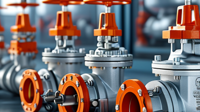
Choosing the right electronic valve can determine whether a system runs smoothly or fails during a critical operation. The decision involves more than matching a product name to a specification sheet. Voltage, current draw, pressure range, flow rate, response time, and connection size must work together. A valve that looks suitable may still perform poorly in a humid cabinet or beside a vibrating pump.
This guide explores seven practical tips for selecting an electronic valve with greater confidence. It considers application conditions, control signals, material compatibility, safety features, maintenance access, and supplier reliability. Engineers should also examine documented test results, traceable certifications, and realistic service-life expectations. A reputable manufacturer should explain limitations clearly, not hide them behind broad performance claims.
Small details matter. A slow response may disrupt a dosing cycle. An incorrect seal material may swell after weeks of chemical exposure. An undersized connector may complicate field repairs. Even experienced teams can overlook these issues when deadlines become tight. I have seen selection decisions change after a simple temperature check or a review of actual fluid viscosity. The process is not always perfectly clean. Datasheets can be incomplete, and laboratory results may not represent operating conditions. Careful questioning helps expose those gaps. These seven tips offer a structured starting point for comparing options, reducing avoidable risks, and choosing an electronic valve that fits both technical requirements and everyday maintenance realities.

Tip 1: Define the application before comparing valve specifications. Identify the fluid, pressure, temperature, flow rate, and required response time. A clean-water loop differs greatly from a compressed-air line carrying oil mist. The U.S. Department of Energy’s Compressed Air System Sourcebook reports that leaks can waste 20–30% of compressor output. Poor valve selection can worsen that loss. Record actual field conditions, not only design assumptions.
Tip 2: Map the complete operating envelope. Note normal, minimum, maximum, startup, shutdown, and emergency conditions. Check how often the valve cycles each hour. The DOE Pumping System Sourcebook estimates that pumping systems use nearly 25% of industrial electricity. A valve that constantly throttles may increase energy use. IEC 60534 sizing methods can support the calculation, but real operating data remains essential. A spreadsheet may still mislead.
Tip 3: Match materials and control behavior to the service. Check corrosion, suspended particles, viscosity, and ambient temperature. Confirm the electrical signal, enclosure rating, fail position, and manual override. In my experience, technicians often focus on flow capacity first. They sometimes miss response delays or incompatible seals. That mistake appears later. A short site trial, pressure log, and maintenance review can reveal those hidden conditions before final selection.
7 Tips for Choosing the Right Electronic Valve?
Match Valve Type to Flow, Pressure, and Temperature Requirements
Start with the medium, then measure the real operating conditions. A valve for clean water may fail with abrasive slurry or thick oil. Check normal and peak flow rates, inlet pressure, outlet pressure, and pressure drop. A simple flow estimate is useful, but it should not replace field measurements. Select a valve with suitable Cv capacity, rather than choosing by pipe size alone. Bigger is not always better.
Choose the control style carefully. Solenoid valves suit quick on-off action, while proportional valves provide more precise flow adjustment. Motorized valves may work better when movement is slower but positioning matters. Check response time, cycling frequency, and available control signals. A 4–20 mA signal can support accurate modulation. Confirm the controller actually produces that signal. Small details matter.
Temperature needs two checks: process temperature and surrounding temperature. Compare both with the valve body, seal, coil, and cable ratings. Also verify the maximum pressure at the highest temperature. I once saw a selection based only on room temperature, which created an avoidable failure. Leave a practical safety margin, but do not oversize blindly. Review material compatibility, installation direction, manual override, and fail-safe behavior. Ask for test data and a clear operating envelope. Then challenge your own assumptions. Your first selection may still be wrong.
Choosing the right electronic valve starts with the materials touching the fluid. Stainless steel may suit clean water, but aggressive chemicals can attack it over time. Check the valve body, stem, seals, and internal coatings separately. One weak component can cause leakage.
Compatibility tables provide useful guidance, but they are not perfect. Confirm concentration, temperature, pressure, and exposure time with technical data. A seal that survives room temperature may harden near a heated pipe. Small details matter. I have seen installations fail because engineers checked the fluid but ignored cleaning agents used later. That mistake is easy to repeat.
Environmental resistance also deserves practical testing. Consider humidity, dust, vibration, salt air, and sudden temperature changes. Select an enclosure with suitable protection, and verify electrical connections against moisture. For outdoor equipment, ultraviolet exposure may weaken plastic parts. For cold locations, condensation can damage control circuits. Test a sample under realistic conditions when possible. Review pressure cycling, thermal cycling, and chemical exposure records before approval. Do not rely only on a polished specification sheet. Your operating environment may be harsher than the laboratory model. Keep inspection notes, including discoloration, swelling, unusual noise, or delayed movement. These observations can reveal compatibility problems before production stops. When uncertainty remains, ask the supplier for independent material data and documented test limits.
Check the voltage and current ratings against your control panel. A mismatch can cause overheating, unstable operation, or early failure. Confirm the valve’s power consumption during startup, not only its normal running state. Check the required control method, such as on/off, pulse-width modulation, or proportional input. The signal must match the controller’s output range. Do not guess. I once saw a valve respond poorly because a 24-volt signal was connected to an incompatible input.
Review response time and flow accuracy for the actual application. A fast valve may be useful for pressure control, but it can create sudden surges in a narrow pipe. Check the medium, temperature, pressure, and connection size before choosing materials. Small errors matter. Inspect safety features, including overcurrent protection, position feedback, manual override, and a defined fail-safe state. Decide whether the valve should close or open after power loss. That decision should follow the equipment’s risk assessment.
Examine the enclosure rating for dust, moisture, and cleaning conditions. A sealed housing may be necessary near washdown areas. Request wiring diagrams, test records, maintenance limits, and replacement procedures from the supplier. Reliable documentation supports safer installation and troubleshooting. Test a sample under real operating conditions before approving a large purchase. Bench results can mislead when vibration, heat, or pressure changes are present. My own preference has changed after field testing revealed slower movement than the specification suggested.
7 Tips for Choosing the Right Electronic Valve
Reliability starts with the operating record, not the catalog promise. Check rated cycles, response time, leakage limits, and failure-mode data. Ask whether testing used temperatures, pressure changes, and vibration matching your site. Look for documented quality controls and traceable test results. Then compare the valve’s duty cycle with your actual process. An oversized actuator can increase wear and energy use. A control cabinet also needs suitable ingress protection and electrical isolation. Small details matter.
Maintenance can quietly decide the purchase. Compare seal replacement intervals, diagnostic access, spare-part availability, and technician training requirements. Choose designs that expose service points without removing nearby piping. Keep a simple maintenance log. It reveals recurring faults better than memory. The U.S. Department of Energy’s Operations & Maintenance Best Practices Guide estimates preventive maintenance can reduce costs by 12–18% compared with reactive work. That figure is useful, but site conditions can weaken it.
Calculate total ownership cost over the expected service life. Include purchase price, installation, calibration, electricity, downtime, labor, spares, and disposal. NIST Handbook 135 recommends evaluating future costs using life-cycle costing, rather than comparing initial prices alone. One uncomfortable point: cheaper equipment may become expensive after one unplanned shutdown. Use supplier data carefully. It may omit cleaning, software support, or lost production. Compare at least three options using the same assumptions, discount rate, and operating hours. Seven checks are practical, but none replaces a realistic failure review.
| Selection Tip | What to Evaluate | Typical Electronic Valve Option | Reliability Considerations | Maintenance Needs | Typical Service Life | Total Ownership Cost Indicator |
|---|---|---|---|---|---|---|
| 1Match the valve to the process medium | Confirm compatibility with water, air, steam, chemicals, oil, temperature, pressure, and contamination level. | Electronic solenoid valve for clean fluids; motorized ball valve for general liquid service; specialized control valve for demanding process media. | High when materials are correctly matched | Inspect seals and check for corrosion, blockage, or leakage. Contaminated media may require filtration. | Approximately 5–15 years, depending on duty cycle and media. | Low to high Incorrect material selection can create premature replacement costs. |
| 2Check pressure, temperature, and flow requirements | Compare operating pressure, maximum differential pressure, temperature range, flow coefficient, and required shutoff performance. | Motorized ball valves generally suit on/off isolation; modulating control valves suit variable-flow applications. | Good when operated within rated limits | Verify calibration, inspect actuator movement, and check for abnormal noise or vibration. | Approximately 100,000–1,000,000 operating cycles for many industrial designs, subject to specifications. | Medium Undersizing may increase energy use, wear, and downtime. |
| 3Choose the correct control mode | Decide whether the application needs simple on/off control, proportional positioning, fail-safe operation, or closed-loop regulation. | Solenoid valve for fast on/off response; motorized valve for slower positioning; proportional valve for variable flow control. | Good Fewer moving parts usually support simpler operation. |
On/off valves typically require less adjustment; proportional systems may require periodic calibration. | Approximately 5–12 years in normal industrial service. | Medium Higher control precision may increase purchase and commissioning costs but reduce process waste. |
| 4Evaluate electrical and communication compatibility | Verify supply voltage, power consumption, wiring, signal type, ingress protection, electromagnetic compatibility, and network requirements. | Common configurations include 12/24 VDC, 24 VAC, 110/120 VAC, 220/240 VAC, analog signals, and industrial communication interfaces. | High when power and signal specifications match | Check cable glands, connectors, terminal tightness, enclosure condition, and communication diagnostics. | Approximately 7–15 years for the actuator electronics under suitable environmental conditions. | Low to medium Standard electrical interfaces simplify replacement and troubleshooting. |
| 5Prioritize reliability and fail-safe behavior | Assess duty cycle, response time, manual override, position feedback, failure mode, redundancy, and environmental protection. | Fail-closed or fail-open actuators are useful where loss of power must place the system in a defined safe state. | Excellent when the failure mode fits the risk assessment | Perform functional tests, inspect feedback signals, and test emergency or manual override features. | Approximately 10–20 years for robust actuators with suitable duty ratings. | Low over the lifecycle Higher initial cost can be justified where downtime or safety risk is significant. |
| 6Compare maintenance access and spare parts | Review seal availability, actuator replaceability, diagnostic functions, service clearance, repair procedures, and spare-part lead times. | Quarter-turn ball valves are often straightforward to replace; integrated electronic control valves may require more specialized service. | Good when components are modular and documented | Typical tasks include leakage checks, actuator inspection, seal replacement, cleaning, and calibration. | Approximately 3–10 years between major service events, depending on cycling and fluid conditions. | Medium Accessible parts and diagnostics can reduce labor and unplanned downtime. |
| 7Calculate total ownership cost, not only purchase price | Include purchase, installation, wiring, commissioning, energy use, maintenance labor, spare parts, downtime, disposal, and replacement costs. | Efficient electric actuators may reduce compressed-air consumption; durable valves may cost more initially but need fewer replacements. | Reliability should be measured across the complete lifecycle | Use preventive maintenance intervals based on cycles, operating hours, and condition-monitoring results. | Typically 5–20 years, depending on design, environment, and maintenance quality. | Lowest long-term cost is application-dependent Evaluate cost per operating year rather than initial purchase price alone. |