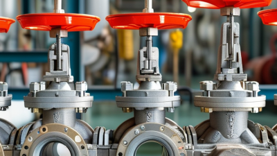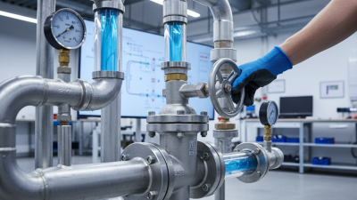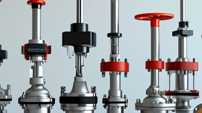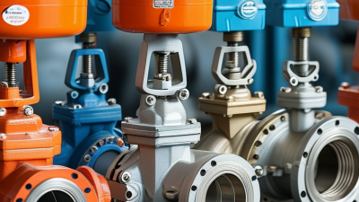
Choosing the right flow control valve is not a simple matter of matching pipe size. It is a decision about movement, pressure, materials, maintenance, and risk. A valve that looks perfect on a specification sheet may perform poorly beside a vibrating pump or a fluctuating process line. Small details matter. A wet handwheel. A sudden pressure drop. A seat worn earlier than expected.
F. G. Shinskey, a respected authority in industrial process control, wrote, “The control valve is the most common final control element.” That observation still deserves attention. The flow control valve directly influences how a system behaves, responds, and recovers. Its trim design, actuation method, pressure rating, and control signal must match real operating conditions. Not ideal conditions.
This guide examines the practical questions engineers and plant managers should ask before selecting a valve. What fluid will pass through it? Is the fluid abrasive, corrosive, clean, or full of suspended solids? What are the normal and emergency flow rates? How much pressure must the valve reduce? These answers often change the recommendation.
Experience also exposes an uncomfortable truth: oversizing is common. A larger valve can seem safer, yet it may operate near its closed position and create unstable control. Undersizing creates another problem. The system may never reach its required capacity. There is no universal winner. The right choice depends on measured conditions, credible calculations, and honest review of past failures. That review can be inconvenient. It is often valuable.
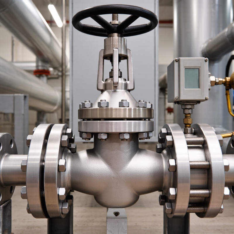
Choosing the right flow control valve starts with understanding its function. A valve regulates fluid speed by restricting passage area. In hydraulic systems, this controls actuator movement and improves operating stability. Needle valves suit precise, low-flow adjustments. Pressure-compensated valves maintain more consistent flow when pressure changes. Simple throttle valves may work well where load conditions remain stable. Small differences matter.
Applications determine the practical choice. Pneumatic equipment often needs smooth cylinder movement without sudden stops. Water systems may require corrosion-resistant materials and easy maintenance access. Process lines can demand accurate metering, low pressure loss, or reliable shutoff performance. Check the fluid temperature, viscosity, cleanliness, and maximum pressure before selecting a valve. A component rated for clean water may perform poorly with abrasive liquid or contaminated oil.
Field experience also shows that installation can change performance. I have seen a correctly sized valve respond badly because a filter was blocked upstream. Keep the valve accessible, follow the indicated flow direction, and protect sensitive components from debris. Measure flow at the actual operating pressure, not only from a catalog value. That assumption can mislead. Leave adjustment range for seasonal or production changes. A valve that works perfectly during testing may become unstable after hoses lengthen, temperatures shift, or several outlets operate together. Careful observation remains part of the selection process.
Choosing the right flow control valve begins with understanding the process, not browsing a product catalog. Identify the fluid, normal flow, minimum flow, maximum flow, pressure, temperature, and viscosity. Record these values at the valve inlet and outlet. Small errors here can cause large sizing mistakes.
A clean water line behaves differently from a slurry containing abrasive particles. Gas service may require attention to compressibility, noise, and pressure drop. For liquids, check the risk of cavitation or flashing when pressure falls sharply. I once reviewed a system sized only for average flow. It worked during testing but struggled during peak demand. Average conditions were not enough.
Control requirements must be equally specific. Decide whether the valve should regulate pressure, level, temperature, or flow. Define the required turndown ratio and acceptable response time. Consider the actuator’s fail-open or fail-closed position during power loss. Also check signal type, available air pressure, installation space, and maintenance access. A fast response sounds attractive, but it may create unstable cycling in a sensitive loop. Sometimes slower control is safer. Material compatibility deserves careful review, especially with corrosive fluids or frequent temperature changes. Ask operators about vibration, sticking, and seasonal process changes. Their experience may reveal conditions missing from the design sheet. Before approval, compare calculated capacity with real operating data, then document every assumption. Some assumptions will be wrong. That is useful to discover early.
Use the following process conditions and control requirements as a preliminary selection guide. Final valve sizing and material selection should be confirmed using the actual fluid properties, operating envelope, applicable codes, and manufacturer calculations.
| Process Condition / Requirement | Typical Operating Characteristics | Suitable Valve Type | Recommended Control Arrangement | Selection Rationale | Important Checks |
|---|---|---|---|---|---|
| General liquid flow regulation | Clean or moderately clean liquid; continuous throttling; moderate pressure drop. | Globe valve or characterized rotary valve | Pneumatic or electric modulating actuator with positioner and feedback. | Provides stable throttling and predictable flow response across a broad operating range. | Calculate required flow coefficient, check valve authority, leakage class, cavitation risk, and available shutoff force. |
| Large-diameter water or low-viscosity liquid service | High flow rate; relatively low pressure loss is preferred; frequent isolation may also be required. | Butterfly valve with a suitable control disc or segmented rotary valve | Modulating actuator for control; separate isolation valve where tight shutoff is required. | Compact, lightweight, and generally economical for large line sizes. | Review minimum controllable flow, disc velocity, torque, seat compatibility, water hammer, and cavitation at high pressure drop. |
| High-pressure liquid throttling | Large pressure reduction across the valve; potential for flashing or cavitation. | Multi-stage globe valve or anti-cavitation trim valve | Modulating actuator with positioner; pressure monitoring upstream and downstream. | Multi-stage pressure reduction limits local velocity and reduces cavitation damage and noise. | Verify vapor pressure, pressure recovery, flashing behavior, trim velocity, noise, vibration, and downstream piping layout. |
| Gas or steam flow control | Compressible fluid; density changes with pressure and temperature; noise may be significant. | Globe valve with characterized trim or high-performance rotary valve | Fast-response pneumatic actuator with positioner; use a fail-safe position based on process risk. | Allows controlled pressure reduction and can be configured for noise and velocity management. | Use compressible-flow sizing; check critical pressure ratio, choked flow, noise, vibration, temperature, and downstream velocity. |
| On/off isolation service | Valve is normally fully open or fully closed; throttling is not required during normal operation. | Ball valve, gate valve, or butterfly valve | Quarter-turn or linear actuator with limit switches and appropriate fail position. | Designed primarily for low resistance when open and reliable shutoff when closed. | Do not use standard isolation valves for continuous throttling unless specifically designed for it; confirm leakage class and actuator torque. |
| Dirty, abrasive, or solids-bearing fluid | Suspended solids, slurry, fibers, or erosive particles; possible plugging and accelerated wear. | Pinch valve, lined diaphragm valve, slurry valve, or abrasion-resistant rotary valve | Modulating actuator only when the selected valve is rated for throttling abrasive service. | Elastomeric or lined flow paths can reduce metal exposure to abrasive or corrosive media. | Check particle size, solids concentration, settling velocity, liner compatibility, minimum velocity, wear rate, and maintenance access. |
| Corrosive or chemically aggressive fluid | Chemical attack may affect the body, trim, shaft, seals, or actuator accessories. | Diaphragm valve, lined valve, or valve constructed from compatible corrosion-resistant materials | Modulating or on/off actuator selected according to the process function. | Separates or protects wetted components from the process fluid where appropriate. | Confirm concentration, temperature, permeation, chemical compatibility of every wetted material, and seal replacement requirements. |
| Hygienic or contamination-sensitive service | Cleanable process; low dead volume; smooth wetted surfaces; frequent washdown or clean-in-place cycles. | Sanitary diaphragm valve or hygienic rotary valve | Pneumatic actuator with position feedback and cleanable accessories. | Supports hygienic design, drainage, and separation of actuator components from the process fluid. | Specify surface finish, elastomer compatibility, drainability, cleaning temperature, sterilization conditions, and sanitary connection requirements. |
| Cryogenic or very low-temperature service | Low temperature; thermal contraction; possible vaporization and cold embrittlement concerns. | Cryogenic ball valve or globe valve with an extended bonnet | Actuator and positioner rated for the ambient and process temperature range. | Extended bonnets help keep packing and actuator components away from the cold zone. | Check material toughness, seat contraction, thermal relief of blocked-in liquid, insulation, packing performance, and venting requirements. |
| High-temperature service | Elevated fluid and ambient temperature; seals, packing, body materials, and actuator accessories may be limiting factors. | High-temperature globe, ball, or rotary valve with suitable packing and trim | Remote-mounted or thermally isolated actuator when required. | Can be configured with high-temperature materials and reduced heat transfer to non-metallic components. | Verify pressure-temperature rating, thermal expansion, packing emissions, actuator temperature limits, and insulation clearance. |
| Very low flow or wide turndown requirement | The process may operate far below normal flow; accurate control is required over a broad range. | Globe valve with equal-percentage trim or characterized rotary valve | Digital positioner with calibrated feedback and an appropriately sized actuator. | Equal-percentage characteristics can provide useful control across changing process gains. | Avoid oversizing; evaluate minimum controllable flow, rangeability, installed characteristic, stiction, dead band, and signal resolution. |
| Fast emergency shutdown or fail-safe action | Valve must move to a defined safe state during loss of power, instrument air, or control signal. | Quarter-turn ball or butterfly valve, or a dedicated shutdown valve assembly | Spring-return actuator with solenoid valve, position switches, and emergency shutdown logic. | Supports rapid isolation and a clearly defined fail-open or fail-closed response. | Complete a hazard review; define travel time, fail position, partial-stroke testing, fire-safe needs, and required integrity level. |
| Flow direction must not reverse | Reverse flow could damage equipment, contaminate another stream, or disrupt pump and compressor operation. | Check valve selected for the actual flow regime | Passive operation; add position indication or a monitored isolation valve when required. | Prevents reverse flow without continuous external control power. | Check cracking pressure, closing speed, slam potential, pulsating flow, installation orientation, and minimum stable flow. |
How to Choose the Right Flow Control Valve?
Choosing a flow control valve starts with the medium, pressure, temperature, and required control accuracy. A globe valve suits precise throttling and stable flow adjustment. A ball valve offers quick isolation, but repeated throttling may damage its seats. Butterfly valves reduce weight and installation space, especially on larger pipelines. The choice is rarely obvious.
Material selection must follow chemistry and operating temperature. Stainless steel resists many corrosive fluids, while carbon steel can lower cost in suitable water systems. Elastomer compatibility deserves equal attention. A failed seal may stop production faster than a damaged valve body. In field commissioning, engineers should compare pressure-drop curves, not only connection size. A smaller valve can create excessive energy loss. The U.S. Department of Energy reports that compressed-air leaks commonly waste 20–30% of system capacity. That makes leakage control important when selecting pneumatic actuation.
Actuation also changes the valve’s real performance. Electric actuators provide accurate positioning and useful feedback. Pneumatic actuators respond quickly and tolerate demanding industrial environments. Hydraulic systems deliver high torque, but they need careful leak management. The IEA’s Energy Efficiency 2023 report places industry at about 37% of global final energy consumption, so small efficiency losses deserve attention. Still, a neat selection matrix can mislead. Actual cycling frequency, fail-safe position, maintenance access, and control-signal quality may matter more than catalog ratings. Test the complete assembly under realistic conditions. That step is often skipped.
How to Choose the Right Flow Control Valve?
Sizing the Valve for Accurate and Efficient Flow Regulation
Selecting a flow control valve begins with measurable operating data. Record the minimum, normal, and maximum flow rates. Note the fluid type, temperature, pressure, viscosity, and density. Do not size from pipe diameter alone. A large pipe can still need a smaller valve. That mismatch causes poor control.
Calculate the required pressure drop across the valve at each operating condition. For liquid service, engineers commonly use the flow coefficient, often called Cv, to connect flow, pressure drop, and specific gravity. For gases, pressure ratio and compressibility also matter. Ask a qualified engineer to verify calculations near choking, flashing, or cavitation. These effects can damage internal components and distort readings. Real measurements help. During commissioning, compare calculated flow with a calibrated meter and adjust the selection if necessary.
Choose a valve that operates near the middle of its controllable range. Avoid valves that remain barely open or almost closed. Check shutoff requirements, actuator response, material compatibility, leakage class, and maintenance access. An oversized valve may hunt, waste energy, and respond slowly. An undersized valve can create excessive noise and pressure loss. I have seen accurate calculations fail when suspended solids or warmer process conditions were overlooked. Recheck assumptions. Leave reasonable margin, but avoid guessing; too much margin is also a design error. Document the final basis so future operators can trust the setting.
Evaluating Installation, Maintenance, Safety, and Total Cost
Choosing a flow control valve starts with the actual operating conditions. Confirm the fluid, temperature, pressure, flow range, and pipe size. A valve that matches the line may still perform poorly if the piping is misaligned. Leave enough clearance for tools and actuator removal. Small details matter. Check the flow direction and keep the manual override accessible. In practical commissioning work, I have seen restricted access turn a simple adjustment into a lengthy shutdown.
Maintenance should be considered before purchase. Can technicians isolate, drain, and inspect the valve safely? Provide nearby shutoff points and clearly marked isolation devices. Follow approved lockout procedures during servicing. Inspect the seat, stem, seals, and connections at planned intervals. Record unusual noise, vibration, or leakage. These signs often appear before failure. My own early maintenance estimates were too optimistic. Dust, moisture, and difficult access increased service time.
Total cost includes more than the purchase price. Calculate energy losses, replacement parts, labor, calibration, training, and possible downtime. A low-cost valve may require frequent adjustments or specialized tools. That can make it expensive over several years. Ask for service intervals, material data, and documented testing. Keep critical seals and fasteners available when delays would affect production. A simple lifecycle spreadsheet can expose hidden costs, although its estimates should be reviewed against real operating records.